Modifying the Hallicrafters SR-2000 High Power Transceiver For Low Power Operation
Three Reasons To Do It
1. It might not be desirable to run a KW at your present location.
2. You will be able to run about 100 watts (low) and 200 watts (high).
3. You will extend the useful life of your RCA 8122 finals and the high voltage capacitors in the P-2000 power supply.
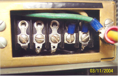
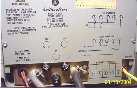
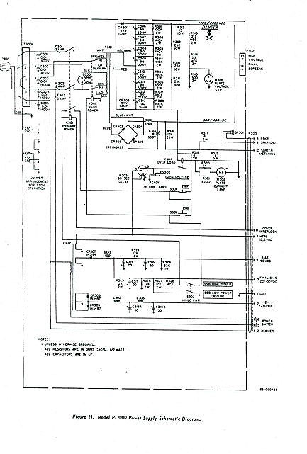
The P-2000 power supply has a high voltage transformer which supplies plate and screen voltage for the 8122 finals. It has dual primary windings for operating 115 or 230 volt AC operation. The receiver power supply also supplies the bias voltage for the finals. It only operates from 115 volts AC. There is a terminal strip in back of the P-2000 power supply and it is accessible when the back power supply cover is removed. It sets up by using a power cord configuration and jumper wires configuration for either 230 volt AC or 115 volt AC operation. The power cord connections are also marked on the fiber board rear safety cover. This modification involves putting the two high voltage transformer primary windings in series on 115 volts AC while the power cord is in the 115 volt AC hookup configuration. This halves the DC voltage for the plate and screens of the 8122 finals. Note: The red neon light on the power supply panel will not go on after the modification due to having only 60 volts AC now applied to each p rimary of the high voltage transformer. Read your voltmeter on your power supply for high voltage on indications. The 8122 final bias voltage has to be lowered so that the plate current can be set to 100 milliamps (resting current). Otherwise you have a 70 lb. QRP rig. A 62,000 ohm resistor is installed at the top terminal of the bias pot to lower the bias voltage to proper level for 100 and 200 watt operation. This modification reduces overall power output to 20% of normal. 500 watts becomes 100 watts on low power position and 1000 watts becomes 200 watts on high power position. These modifications can easily be changed back to normal operation of the SR-2000 Hurricane when desired.
CAUTION: UNPLUG AC POWER SUPPLY CORD BEFORE TOUCHING THE TERMINAL STRIP, WHICH IS ALWAYS LINE VOLTAGE HOT WHEN POWER CORD IS PLUGGED IN. Change the 3AB 12 amp fuses to 3AB 5 amp fuses for this modification. 12 amp fuses are now too high, since the transceiver will draw considerably less current in this configuration. After modification set final bias current to 100 mills. See Diagrams. Note: The AC line cord is set for 115 volt AC operation. Rear P-2000 Terminal Strip Modification jumper wire placement: Terminal 1 to 5 & Terminal 2 to 3


Remove wire from top of bias pot and insert 62,000 ohm half watt resistor between bias pot top terminal and removed wire. Solder in resistor as per diagram.
This completes the modification. Load and tune the SR2000 as you do normally. Edited by Barbara R. Shure

P-2000 Rear Cover

P-2000 Schematic

HOT LINKS:
Home
|
Search QTH.NET Lists
|
Blast from the Past
|
Photo Archive
|
For Sale/Swap
Click here
to contact webmaster.
Click here
if there is no left-side menu frame.
This page last updated 30 Nov 2024

