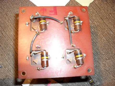
I marked out on the old boards all of the connections and the direction they were installed. I then checked the web and found designs for power supplies that were similar and used those as a template for my circuit boards. I did have several schematic and pc board programs but the work was already done for me so I just made the changes I needed in paint and made a few copies to see how they would fit in the supply.
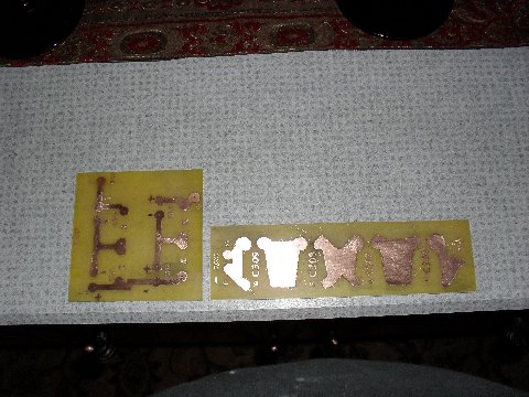
Once I was done sizing, the above is what I ended up with. I etched the boards and drilled the holes and test mounted everything in the supply.
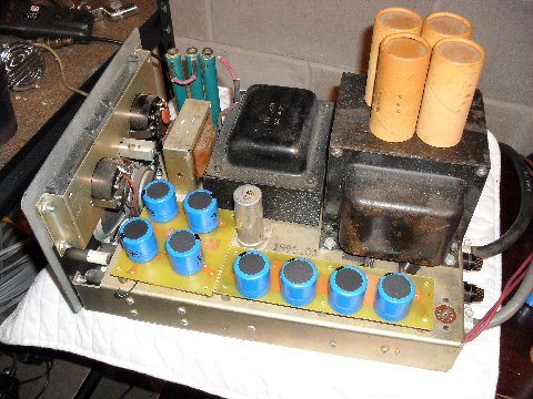
As you can see, the new snap in caps are scrawny compared to the old ones. You can see the cap covers on the transformer which will be hot glued over the new caps so it looks right from outside. BTW, I heeded a warning from Sandy and loosened the bleeders so manipulating the supply wouldn't damage them.
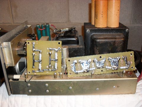
Here is a shot of the bottom, this shows the equalizing resistors (Harbach electronics 10 for 5 bucks shipped) They are metal film types and work great. Its now ready to try out.. Below is a shot with the cap covers placed over the caps to show how it would look. The caps are from Mouser, 8x $3.85 or so from what I remember. (Buy 10 -- it is cheaper)
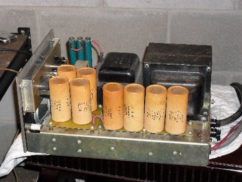
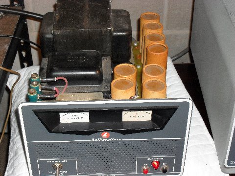
Above is a picture of the supply in low power with the cap covers placed (but not glued in yet) over the top of the caps. This gives you a general idea of how it will look although they are not positioned correctly over the new caps. You can see about 1700 +/- low power on the plate volts meter. Now that it works, I will remove the boards and clean the chassis and touch up the transformers to spiff things up and then glue the covers on and reinstall everything. I also replaced all of the caps underneath the supply as well. Below are the PC board layouts. The two boards are a 3.75 inch square board and a 7.25 inch x 2 inch rectangular board. I simply printed a dry run with my printer with regular paper and matched them up to the cut PC boards and adjusted the size in printer preferences if its needed. You will see that the patterns I supplied are relatively spot on when you bring up printer preferences showing those exact sizes in the printer box. Once its sized up, I used Printed circuit transfer film called "Press N Peel Blue" available on the web. Use a laser printer to print the pattern on the transfer paper, then iron the transfer paper onto the boards. Any touch ups can be done with a black sharpie pen if needed. Once you are satisfied, etch the boards, scrub them clean and match them up to your old ones for the holes.
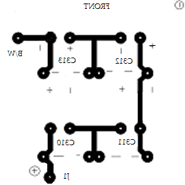
psb4x4inchApsREVFINALc template

cap board2x7inchApsREVFINALc template

HOT LINKS:
Home
|
Search QTH.NET Lists
|
Blast from the Past
|
Photo Archive
|
For Sale/Swap
Click here
to contact webmaster.
Click here
if there is no left-side menu frame.
This page last updated 30 Nov 2024

