Ketner's descriptions of the HT18 and work on it.

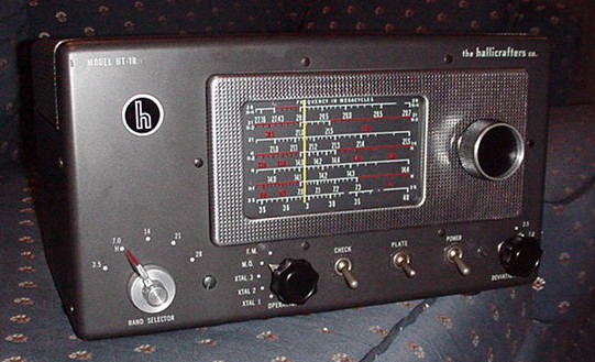
Front View of the HT-18 Prototype.
I received 2 HT18 sets hoping to get one good one. Now it looks like
there will be two, and perhaps an interesting development with one of
them. When I began working on the first one, I noticed that there were
machinist's scribe marks all over the chassis, marking drill holes, no
screened labels on tube sockets or terminals, different knobs on the
front panel, different colored dial pointer (yellow), and slight
variations in cabinet mounting screws. The other presumably standard
unit had no scribe marks, had screened tube socket and terminal labels
on the chassis, had a red dial pointer, and the standard set of knobs.
This led me to suspect that the one I had begun restoring was a
prototype of some sort. So I set about cleaning and lubing it, and
placing it into working order without any noticeable changes from the
condition received.

Inside Top View of the HT-18 Prototype. Click here to enlarge image.
Under chassis I replaced about 4 wax paper caps and disconnected the
can capacitor because it tested bad (but I left it on the chassis) and
installed 2 axial lead electrolytic caps, installed a new power cord
through a neoprene grommet, put in a good set of tubes. I cleaned up a
few ground connections and a few iffy looking solder joints. I then
brought it up slowly on my variac. When at working voltage I got 5 watts
into a dummy load on 7mhz, so it seems to be working ok. There are no
topside or outside mods visible on the unit.

Rear View of the HT-18 Prototype. Click here to enlarge image.
The second HT-18 is surely a production unit, and it seems
restorable, so I will probably go ahead and bring it up to speed soon.
- Ken Ketner, KA5ELD, ketner@arisbeassociates.com

HOT LINKS:
Home
|
Search QTH.NET Lists
|
Blast from the Past
|
Photo Archive
|
For Sale/Swap
Click here
to contact webmaster.
Click here
if there is no left-side menu frame.
This page last updated 30 Nov 2024

