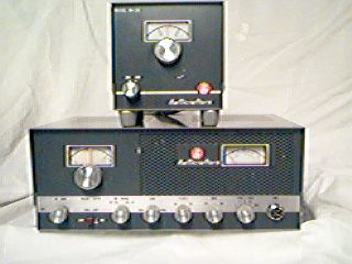
Doug Moore, KB9TMY
 |
SR-46A
Restoration Project Doug Moore, KB9TMY |
 Editor's Note: Rig pictured is not actual rig restored |
I received this radio with a Shure PTT microphone. The radio was in average condition, with original knobs. This radio has a combination 120VAC / 12VDC power supply, which is selected by virtue of an octal connector on the rear panel. (Like the Jones plugs on the old Gonsets.) As received, there was a non-polarized line cord fed through a small hole in the back of the chassis and soldered directly to an internal tie point. There were some signs of minor butchery, but it appeared to work - sort of. The transmitter dropped out intermittently. Output was about 10 watts. The receiver appeared somewhat unstable, and the squelch didn't work. Meter indication on transmit seemed meaningless so I used an SWR box to tune the transmitter. The meter circuit may have problems, or the problems may be elsewhere. Chassis was fairly clean; case had been repainted, and could use repainting again. |
I ordered a schematic from
W7FG manuals. Using the tube guide pasted inside the chassis
cover, I discovered a 12BH7 in the socket where a 12AT7 is
supposed to be. This is the receiver oscillator and first mixer.
Tried a 12AT7, but obviously the front end will have to be
realigned when I change the tube. While waiting for the schematic,
I made a proper line cord adapter with a grounded line cord, and
fixed the transmitter output tuning capacitor, which was loose.
This was a standard Johnson variable, with two threaded studs
swaged to a ceramic base. The studs were loose, so the capacitor
was removed and placed in a vice. A couple of taps on the swaged
studs with a piece of º" steel rod tightened them up nicely.
Removed on/off volume control and disassembled it in order to
clean the switch which was intermittent. I would have just
replaced the unit, but it was a 1 meg pot with a 10 amp switch -
not easy to find these days. (The switch has to carry the full
current when the 12 volt vibrator supply is used.)
I received the manual from W7FG. The schematic is for an SR-46,
and I have an SR-46A. The difference appears to be the addition
of the squelch control and associated circuitry. I tried to trace
the squelch circuit, but got lost when the wires entered a laced
wiring harness. It appears to be a simple diode gate gizmo in the
audio line, probably run from the AVC voltage. Fired up the unit
again and noticed one tube seemed to be glowing brighter than
usual. On inspection, tube turns out to be a 6U8 instead of a
7059. No wonder, there's 12 volts on a 6 volt tube. Couldn't find
any 7059's in my tube stock. I ordered one from vactubes.com plus
a spare 7551 final. Tried again to trace the squelch circuit
while waiting for the tube. No further electrical work will be
attempted until I have all the right tubes in this thing.
Got all the tubes and finally found time to get back to the
project. Replacing the 6U8 with the 7059 appeared to solve the
transmitter problem. Transmitter output waveform looked good into
a dummy load, although modulation was only about 40%. I think
this is about what would be expected from the circuit, which uses
a single ended 12AQ5 as the audio output and modulator. The meter
indication on transmit now made some sense. Armed with the
schematic and alignment instructions, I now attempted to align
the receiver with the proper 12AT7 oscillator / converter tube.
No matter what I did, the first mixer had a tendency to oscillate
at the first IF frequency. The previous owner had apparently
rebuilt the first mixer transformer. I inspected the transformer,
and it looked like it was properly made, so I looked for the
cause elsewhere. After several hours of trying various tricks,
including adding a shield, I went back to the transformer. On a
hunch, I tried reversing the phase of the primary. In theory,
this should have made no difference, but amazingly, the
oscillation disappeared and the set aligned normally.The
sensitivity was amazingly good for a set of this vintage. The
local oscillator covers the tuning range in two segments,
switching in another coil in parallel to cover the lower 2mhz.. I've
never seen such an arrangement, but it does work. Final
oscillator touchup needs to be done with the chassis in the case,
as the case adds some capacitance to the circuit. The trimmers
are accessible by opening the top.
| After the set was all tuned up,
I connected an antenna and began tuning around. Heard a
lot of cordless phones below the 50mhz mark on the dial,
and also apparently as an image on the 52-54mhz range.
The RF amplifier is a nuvistor, fixed tuned and
neutralized, which accounts for the sensitivity, but alas,
also the marginal image rejection. From my Chicago
Suburbs QTH, I didn't hear a single 6m AM signal. I did
hear a few FM signals, which I could demodulate by
detuning slightly and using slope detection. I had to
"arrange" a contact with another local ham who
has an old Gonset 6m transceiver to verify the
transmitter performance. All seemed well, so I put the
set back in the case. Never did figure out why the
squelch control didn't work - will save that for a rainy
day. |
 |
The rainy day came much later, when a
friend was looking for a 6m rig to monitor band openings. For
this purpose, the squelch needed to work, so I obtained a
schematic for the SR-46A from Tony Deprato, the HCA librarian.
Armed with the actual circuit, it didn't take long to trace the
problem. One end of the squelch diode is connected to the screens
of the IF amplifiers, through appropriate resistors and
decoupling capacitors. This point sits at about 50 volts with no
signal, and rises on signal due to the application of negative
bias from the AVC. The other end of the diode goes through
another large resistor to the arm of the squelch potentiometer,
as well as being capacitively coupled to the volume control.
Since this is the cathode end of the diode, this voltage needs to
be higher than 50 volts to reverse bias the squelch diode and cut
off the audio. It measured zero volts. The pot derives it's
voltage from a 220K resistor connected to the plate supply of the
IF stages. One end of this resistor had about 60 volts, the other
end had zero. When I disconnected the wire from the squelch pot,
the voltage went up to what it should be. Since the position of
the squelch pot did not affect the voltage in any way, I
concluded the clockwise end must be shorted to the chassis. Sure
enough, with all the wires from the pot disconnected, I read
about 3000 ohms from this pin to the chassis. I replaced the pot,
and the squelch worked perfectly.
Originally, I was afraid this set would just sit on a shelf,
since there is little or no 6m AM activity in my area. Happily,
it is going to a place where it will be used. I think in its day
it would have compared favorably to the Gonset and Lafayette
equivalents, except perhaps for image rejection.
This page last updated 31 Mar 2001.