 |
S-19R Restoration
Project Doug Moore, KB9TMY |
 |
S-19R Restoration
Project Doug Moore, KB9TMY |
Restoration
Notes – Hallicrafters S19R
August 11, 2000
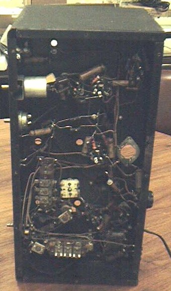 Bottom of Chassis After Initial Cleaning, Before Rebuild |
As received, the receiver
appeared to have all the parts. The bandspread bezel and
"glass" were loose, the two tube shields were
loose inside the case, and the overall case and chassis
were very dirty. Upon inspection of the under chassis, I found a kludge capacitor in parallel with the first section of the twistlock electrolytic, and there were quite a few spider webs. There were also lots of old paper capacitors, probably leaky, old style body/end/dot resistors, and a piano tuning felt wedge jammed in the BFO coil. Neither of the tuning dials worked due to the age of the dial cord, which though intact, was stiff and brittle. Since there is no removable panel, it appears the complete tuning assembly must be removed to restring the dial. No attempt was made to apply power. It is a certainty that the twistlock can is bad, so this will have to be rebuilt or replaced. Not sure yet how to approach cleaning up this beast – maybe remove the tubes and tuning assembly, and start from there? The tuning capacitors, shafts and dial plates will need cleaning, and it will need new dial cords. |
To start, the kludged add-on
capacitor was removed, and most of the spider webs cleaned out. A
schematic was available on the BAMA website. This schematic was
nearly the same as my unit except for the tube complement. On my
receiver, a 6K7 and a 6Q7 are used instead of the 6SK7 and 6SQ7
shown in the 19R. I have since discovered there were two runs of
S-19R, and mine is the earlier run. I figured a logical place to
start would be with the dial cords. Since the whole assembly was
quite dirty, and had obviously had several "quickie"
fixes applied, (like tape around the shaft) it looked easiest to
remove the whole works. This is accomplished by unsoldering two
wires from the tuning capacitor on the bottom of the chassis, one
ground braid on the top side, then removing the main dial, knobs
and the mounting nuts holding the tuning assembly. Two of the
mounting studs have ground lugs attached. These have two nuts,
one holding the tuning assembly, and one holding the lug. (Remember
this when you re-assemble.) Once this is all loose, you need to
loosen the setscrew on the bandspread dial and push it back
slightly on the shaft, so it will clear the top of the case. The
entire tuning mechanism can then be removed and serviced.
Once out of the chassis, I made a sketch of the dial cord
stringing, such as it was. The old cord was removed, and the
tuning assembly frame was stripped down to bare metal by removing
the shafts and tuning capacitor. This frame was scrubbed with
kitchen cleanser, rinsed and given a light coat of deoxit. The
shafts were cleaned and polished, then trued up slightly. The
tuning capacitor was sprayed with WD-40, scrubbed carefully with
a brush, then rinsed and blown out with an air hose. A bit of
deoxit was sprayed on the rotor wipers, and a drop of silicone
grease was applied to the two bearings. The tuning shafts were
then re-installed in the metal bracket, using a small amount of
silicone grease in the bearings. The shorter, single diameter
shaft goes in the top bracket, and the other two (which are
identical) go in the bottom. The tuning capacitor was remounted
and checked to insure its shaft was parallel with all the other
shafts.
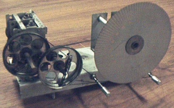
Tuning Assembly After Rebuild and Restringing.
Next job was the
restringing. For the cord I used my standard 45lb Dacron fishing
line. I started with the main tuning, since it is strung behind
the bandspread cord. Initially, I strung it exactly like the
original, with both ends of the cord tied to the spring. After
trying it out this way, I felt there was not quite enough
tension, because one end wraps a full turn around the tuning
capacitor pulley, while the other end only goes about a quarter
turn around the pulley. The spring cannot take up the slack on
the short end of the cord because of the friction of the long end
around the pulley. So, I undid the thing, and re-strung it
starting with a tied loop attached to the spring lug on the
pulley, wrapping around the pulley one and a half turns, then
around the tuning shaft two turns, then back to the tuning
condenser pulley, through the hole in the pulley then tied to the
spring with as little slack as possible. After gluing the knot,
the other end of the spring was attached to the spring lug, and
the whole thing worked much better.
The bandspread cord was done in a similar manner. I was a little
surprised that the cord in the original stringing did not do a
complete wrap around the pulley on the bandspread dial. I tried
stringing it with a full wrap but it seemed cumbersome and I wasn’t
sure I could move the dial back far enough to get the assembly
back in the cabinet. So, I stuck with the original stringing,
except for using a tied loop to the spring lug on the long end.
This appeared to be the way Hallicrafters did it originally, and
if it worked for them it should work for me. I figured the worst
that could happen would be that the bandspread dial could slip,
but it could be easily corrected by opening the top of the case
and turning it slightly. On this receiver, the bandspread dial is
not marked in frequency, but with just a 0-100 logging scale.
The tuning assembly was now ready to reinstall in the main
chassis, but first I needed to do some cleanup. I removed the
remaining knobs, and the old twistlock can. Due to the fading of
the old wire colors, and my own partial color blindness, (I can’t
tell a 100 ohm resistor from a 1meg without an ohmmeter.) I
marked the removed wires with stick-on numbers, and made notes as
to which section of the capacitor was connected to which number
wire. I started the cleaning with a mild dishwashing soap and
water, scrubbing the chassis with a brush and being careful not
to get any water near the speaker, transformer or IF cans. There
was a lot of "gook" around the area where the old
twistlock had been mounted; indicating it had been leaking for
some time. This stuff required a little more aggressive cleaner
to remove, but Ajax seemed to work. The corroded spots on the top
of the chassis and on one side of the chassis now became very
visible. The front panel, however, looked reasonably good. I
decided to address the cosmetic issues as needed during the re-assembly
phase. After drying the chassis, I had a close look at the
speaker. The cone looked quite dry and brittle, and I made the
mistake of touching it, only to have my finger go right through.
Oh well, live and learn. Time to remove the speaker and have it
reconed. The speaker is held to the panel by four ornamental
screws, rubber grommets and nuts. Six wires pass from the speaker
and output transformer through the chassis. These were marked as
described above, and then the entire speaker assembly was removed.
All rubber grommets were either turned to goo or brittle.
Fortunately, these are still readily available. I saved samples
of the sizes I needed and tossed the rest.
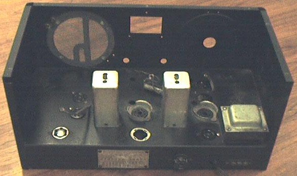
Top of Chassis After Removal of Tuning Assembly and Initial
Cleaning
Next I installed the new
twistlock, and decided to replace all the old paper and wax
capacitors. Most of these were no problem, with the exception of
C4 and C5. One end of C4 connects to a terminal on the front deck
of the bandswitch, which was virtually inaccessible. The wiring
is tight here and it did not appear feasible to remove or rotate
the bandswitch. I elected to cut the bandswitch lead close to the
capacitor, strip off a bit of the sleeving, slip on a piece of
heatshrink tubing, then splice and solder the lead from the new
capacitor to the stub. After this, the heatshrink was slipped
over the splice, and a bit of heat applied. One end of C5 goes to
a very crowded ground lug, the same one that carries a ground
braid through the chassis to the tuning capacitor. Even the
original assemblers couldn’t get all the leads through the
hole in this lug, but the real problem is the other end of C5,
which goes to the bottom terminal of an antenna coil. Again, this
connection is nearly inaccessible. Though this capacitor could be
relocated, it’s placement made sense RF wise, and I didn’t
want to second-guess the original designers. After some study I
elected to temporarily remove one wire from the adjacent coil.
This allows access to the lower coil terminal, providing you have
a small pencil-tip iron. Capacitor C22, which goes from one side
of the AC line to the chassis, was replaced with a capacitor
certified by UL/CSA for this type of service. A one lug terminal
strip was mounted using one of the transformer mounting screws so
that a fuse could be added in series with the hot lead from the
line cord. The old line cord was replaced with a somewhat more
rugged polarized cord. I checked the values of the old dog bone
resistors, and amazingly, didn’t find any that were off by
more than 20%, so I left them alone.
While the speaker was out for reconing, I did some touch up
painting on the chassis and side panels using flat black Krylon
spray. The front panel looked pretty good after a light rubdown
with WD 40. There were some white paint specs here and there,
which I touched up by spraying some Krylon on a Q-tip and dabbing
it on. (Someone once said since these spots are so common on old
radios, people must have used them in place of a tarp when
painting.) I cut out a new bandspread "glass" from thin
plastic, and scribed a line down the center. I tried inking this
line, but decided I liked the scribe better. I then installed new
grommets in the tuning assembly holes, loosened the setscrew on
the bandspread dial and moved it back a bit, then remounted the
tuning assembly and reconnected the wires. Be sure to use plenty
of heat on the shield braid connection, and don’t forget the
solder lugs that go on two of the mounting studs. After the
tuning assembly is mounted, move the bandspread dial forward and
tighten the setscrew. NOTE: Failure to move the bandspread dial
back during tuning assembly removal and re-installation may
result in cracking the plastic dial. Also, beware of the screw
head holding the bandspread bezel, it can scratch the dial.
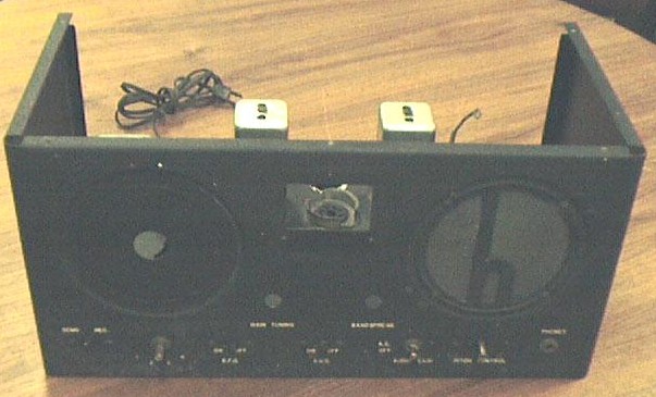
Front Panel After Initial Cleaning (Note White Paint Spots).
The headphone jack is intended for high impedance headphones, being fed by C15 from the output tube plate. If you want to use low impedance phones, you will have to install a new headphone jack with an isolated SPDT switch, and do some rewiring. This is best done when you are reinstalling the speaker, as some connections between the output transformer and the speaker have to be rearranged.
|
When the speaker arrived, I installed new grommets, mounted it back in the case, and reconnected all the wires. The knobs were cleaned up and reinstalled. A bit of white crayon restored the white dots on the audio gain and BFO pitch knobs. I used Naval Jelly and fine steel wool on the main dial, with results that were fair. (Rock Sea is supposed to be working on a new dial for the S-19.) The plastic pointer and spacer washers for the main dial were reinstalled. The tubes were unwrapped and tested. Only the rectifier, (an 80) was reinstalled for now. |
The receiver was plugged
into a variac and the B+ voltage monitored. The variac was turned
up to the point where the rectifier became hot enough to do its
stuff. Everything was carefully watched for signs of
spitzensparken and fusenblowen. So far, so good. With 70 volts AC
from the variac, the B+ read about 130V. With 120V input, the B+
was reading almost 300V. The rest of the tubes were then plugged
in, at which point I noted I had a metal 6K8 instead of a glass
one. The converter tube shield was therefore not required, which
is why it was loose when I first inspected the receiver. The
shield IS required for the 6K7 IF amplifier.
I was now ready for the first test. I turned the radio on with
the variac set to 100V. After the set warmed up with still no
smoke, I turned up the volume and touched a pencil to the top of
the audio gain control. Some hum was heard, indicating the
amplifier and speaker were working. I then switched to Band 1,
jumpered A2 and GND on the antenna terminal strip, and connected
about a 10ft. piece of wire to A1. On tuning, several AM stations
were heard and the sound quality was pretty good. Turning on the
BFO switch, I was able to adjust for zero beat with no problem.
Under these conditions, with the variac turned up to 120V, the B+
from the rectifier read 255V. No specific voltage is called out
on the schematics I had, but the output of the optional vibrator
supply was shown as 260V, so I figured I was close. I played the
radio all day at 120V and all seemed to be in order. The
transformer laminations read 58 degrees C after 7 hours. A bit on
the warm side, but not what I would consider hot. It’s a
personal decision whether to run this receiver through a voltage
reducer, setting the input voltage at 110V, which was probably
its design center.
While "burning in" the radio, I cleaned, straightened
and repainted the top and bottom cover panels. The "feet"
on the bottom were replaced after the paint dried. Apparently,
there was some kind of paper legend once attached to the bottom,
which may have identified the trimmers, but this was missing on
my particular set. It may be that the purpose of this was more to
cover the access holes than inform, I really don’t know. The
trimmer information is included in the schematic and alignment
instructions anyway.
Satisfied that nothing was going to burn up, I proceeded to align
the set according to the instructions. This set uses "padder"
capacitors to adjust the low end tracking on bands one and two,
rather than adjustable inductors as used on later radios. High
end tracking is set by trimmers as usual. There are no padders
for bands three and four, so low end tracking is set by design,
and hopefully will be pretty close. During alignment, keep the
signal generator output as low as possible, and set the
bandspread at MINIMUM capacitance. Mine tuned right up with
little difficulty, although the tracking on band four was not
perfect. I adjusted trimmer CH for best compromise around the 10
meter area. The final alignment should be done with the bottom
cover in place, as it influences the inductors.
After alignment, the performance of the radio was surprising,
considering this model was made about 1938, and had all but one
of the original tubes. Buttoning it up, I took it upstairs and
hooked it to the attic dipole. The performance on bands 1 and 2
was just about the same as my SX-117, though not with as much
selectivity. It was possible to copy sideband on 75 meters with
good intelligibility. Tuning sideband with just a BFO is a bit
tricky, but not impossible. Performance on band 3 was definitely
poorer than the 117, but still not too shabby. Performance on
band 4 was slightly better than poor. It could be that a new 6K8
would help, but since this receiver is to be used mainly for SWL,
I wasn’t too concerned. To me, it was amazing that it did as
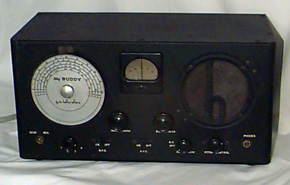
well as it did for a 1938 radio with no RF stage. The finished
product didn’t look like it just came out of the box, but it
sure looked a lot better than it did when I started, and was
quite presentable. The weak spot is the main dial. If a
replacement scale becomes available, I’ll probably buy it.
 |
It is my hope that these notes assist you in your restoration of a similar receiver. There is a lot of history in these early receivers. Who knows what sounds came out of its speaker? The celebrations on VE day? Truman’s speech when he fired General McArthur? Cold war propaganda from Radio Moscow? I know I’ll think about this every time I play this old Hallicrafters. |
Doug Moore - KB9TMY (formerly K6HWY)
This page last updated 16 Mar 2002.