 |
HT-46
Meter Replacement Tony Dolby, F5VBY/G3TZH |
 |
HT-46
Meter Replacement Tony Dolby, F5VBY/G3TZH |
Hi - I have the HT-46 Tx and the companion SX-146 Rx which I bought in excellent condition except that the meter on the Tx was burnt out. I have been searching now for some considerable time for a replacement without success and note that other people are advertising for the same item.
 |
I have recently
utilised another Meter which I obtained from Fair Radio (fairadio@wcoil.com ) which is advertised on Page 34
of their catalogue and listed as: FS=200 UADC clear
plastic 2.5" W x 2.3"H meter with non-linear
scales for 0-10 watts, 0-100 VSWR, 0-100% Mod, used and
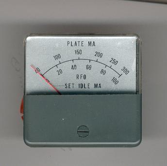
priced at $4.00 With a little ingenuity a perfectly good replacement can be made. The existing meter should have the scale removed together with the front cover which should be set aside. Remove the front panel from the TX and rework the hole to take the new meter which has a larger barrel and 4 retaining screws. |
Remove the front of the new
meter and carefully remove the existing meter scale gaining
access to the meter interior. Unsolder the two wires from the
back terminals making sure not to damage the movement or the
meter needle. Undo the two retaining screws holding in the
movement and remove. Work can now be carried out to fit the meter
body to the front panel and to slightly reduce the width of the
case (approx. 1,5mm per side) so that the old front cover fits.
Mine was done using a fine hacksaw used for modelling. Don’t
forget to round off the corners otherwise it wont fit! The old
Hallicrafters meter scale can be used as a guide.
Re-assemble the meter to the point when you fit the scale and at
this stage the old scale must be cut across the bottom so that it
can be stuck onto the new meter scale and clear the mounting
screws. This is necessary because the new meter has a different
scale mounting. I used a sturdy pair of kitchen scissors being
careful not to distort the scale and stuck it to the old scale
using Super-glue! When this is done the scale can be carefully
slid under the needle and the two retaining screws fitted.
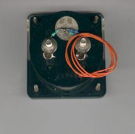
| The meter will need to
be shunted in order to work the same in the bridge
circuit and the shunt resistors can be clearly seen in
the picture of the rear of the meter. The new meter does
not have provision for illumination and I drilled a small
hole at the bottom side of the meter case so that a pair
of wires attached to a small Pea-bulb could be brought
out to the rear. The bulb was attached to the case at the
bottom left corner (looking at the front) with a spot of
contact adhesive. The whole assembly can now be put back together and the existing feeds to the meter attached. |
 |
Note that procedures for calculating the shunt are quite straight forward and can be found in the ARRL handbook together with a safe way of determining the internal resistance of the new meter.
This page last updated 1 Sep 2001.